ASSEMBLY HOW TO
ASSEMBLY HOW TO
FASTENERS AND PRECISION COMPONENTS
How to Determine the Proper Disc Spring Stack Configuration
Shorter stacks are more efficient, which is of particular importance for dynamic applications. As a result of friction between the Disc Springs as well as the guiding mandrel or sleeve, the Disc Springs at the moving end of the stack tend to deflect more than the Disc Springs at the opposite end. Using the largest practical diameter Disc Spring will reduce the number of Disc Springs per stack and the total stack height. It is recommended that the overall stack height does not exceed 3 times the external diameter of the Disc Spring or 10 Discs in series. If required, taller stacks can be divided with flat washers to provide stability.
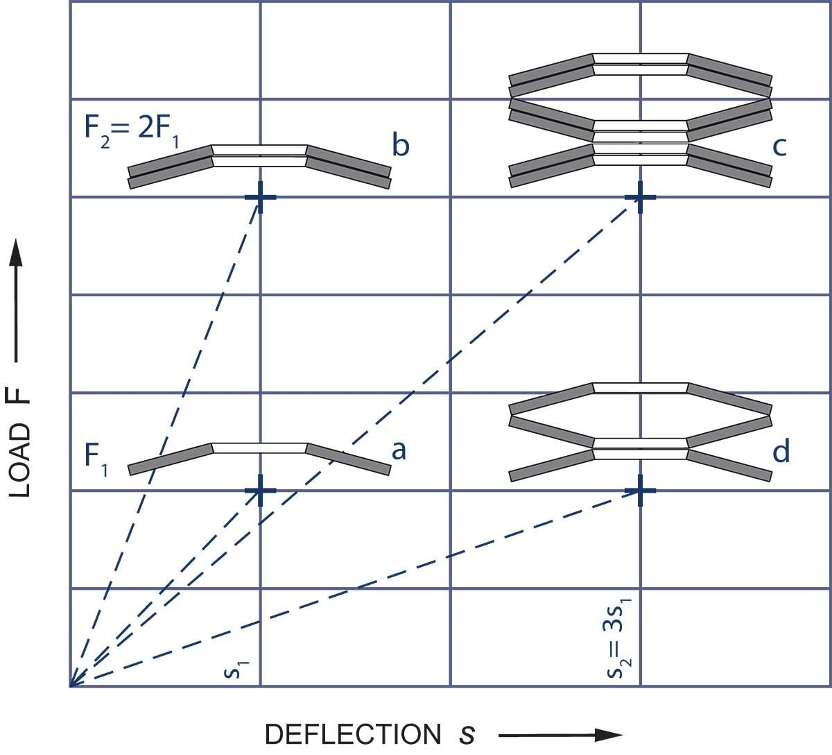
Progressive Load Curves
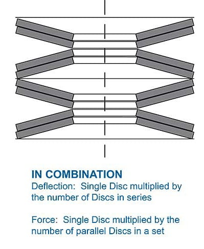
Progressive loading can be obtained by assembling the stacks in which the Disc Springs will deflect consecutively when loaded by:
- Stacking single, double and triple parallel sets in series.
- Stacking Disc Springs of various thickness in series.
- Deflection of the weaker Disc Springs needs to be limited to avoid over-compression, while the stronger Disc Springs or parallel sets are still in the process of compressing.
This image above shows Disc Stacks with progressive characteristic load curve and stroke limiters to avoid overload.
Pre-Stacked
The process of installing Disc Spring Stacks in a production environment is generally a manual, time-intensive process that introduces an opportunity for errors in the stack configuration. Rather than configuring the stack of Disc Springs manually, Pre-Stacked Disc Springs (greased or ungreased) are available from manufacturers. These stacks are packaged in shrink-wrap with a perforated tab, allowing a simple installation process that saves time and helps mistake-proof the assembly process.
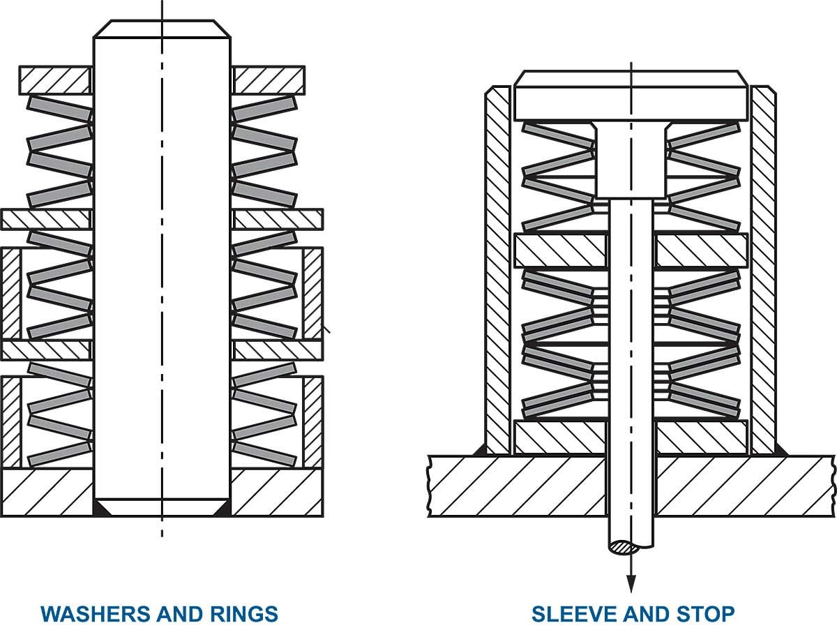
Stack Guidance
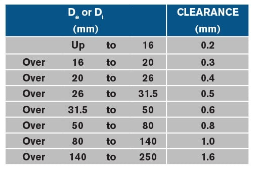
To keep the Disc Springs in position, the stacks need guiding. The preferred method is internal guidance, such as a rod/mandrel, through the inside diameter. In the case of external guiding, a sleeve is suggested. In either case, the guiding component should be case hardened to 58 HRC with a depth of not less than 0.6mm with a surface finish of ≤ 4 microns.
Since the diameter of the Discs change when compressed, the following clearance values are recommended:
By Darren Snell – Disc Spring Product Engineer
SPIROL
Disc Springs are conically-shaped, washer-type components designed to be statically loaded either continuously or intermittently, or dynamically subjected to continuous load cycling. What makes Disc Springs unique is that based on the standardized calculations of DIN 16984 (formally DIN 2092), the deflection for a given load is predictable.
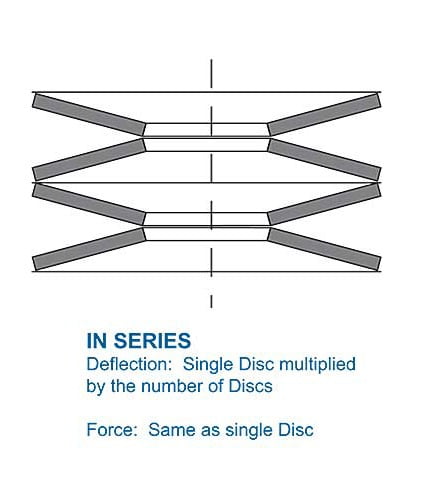
Optimal Disc Spring performance is achieved with the working deflection between 15% and 75% of full deflection as it is in this range that the theoretical characteristics and measured results most accurately match. If a single Disc Spring is not capable of the force/deflection characteristics the application requires, Disc Springs stacked in series, parallel or combination can be used.
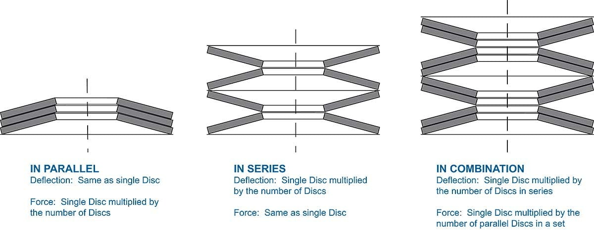
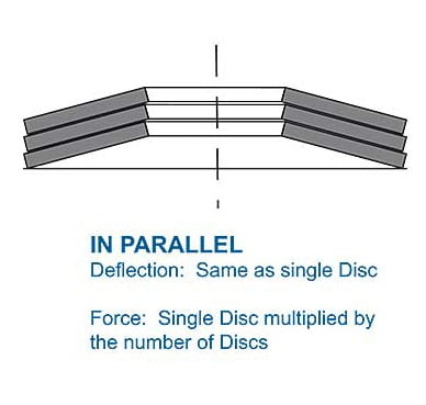
Methods of Stacking
For Disc Springs stacked in parallel or combination, friction between the parallel Disc surfaces needs consideration. Many factors affect the amount of friction of the Disc Springs Stack. These include, but are not limited to, surface roughness, number of Disc Springs stacked in parallel, and amount of deflection. A reasonable allowance is 2-3% of the force for each sliding surface – a greater force for loading and a lesser force for unloading. Disc Springs stacked in parallel should be well lubricated and limited to a maximum of 3-4 Discs to reduce the deviation from the calculated to measured characteristics. Disc Springs stacked in parallel have increased self-dampening (hysteresis) characteristics.
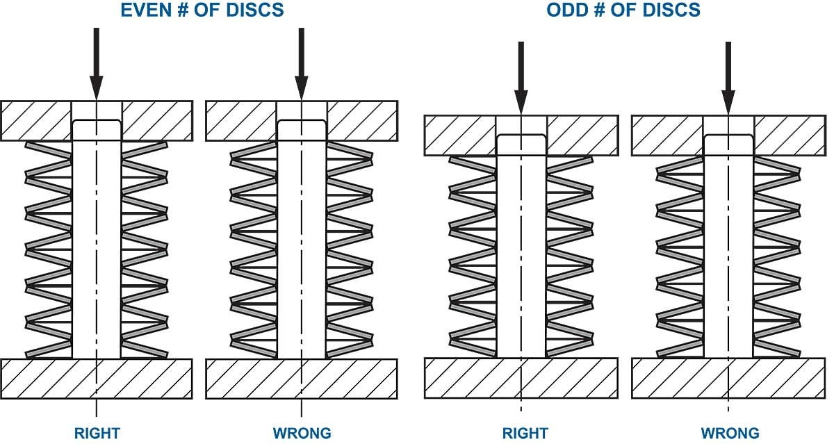
Stack Construction
Having both ends of the stack resting on the larger outer edge of the Disc is desirable. If this is not possible, such as with an odd number of Discs, the larger outer edge should be arranged to be on the end to which the force is applied.
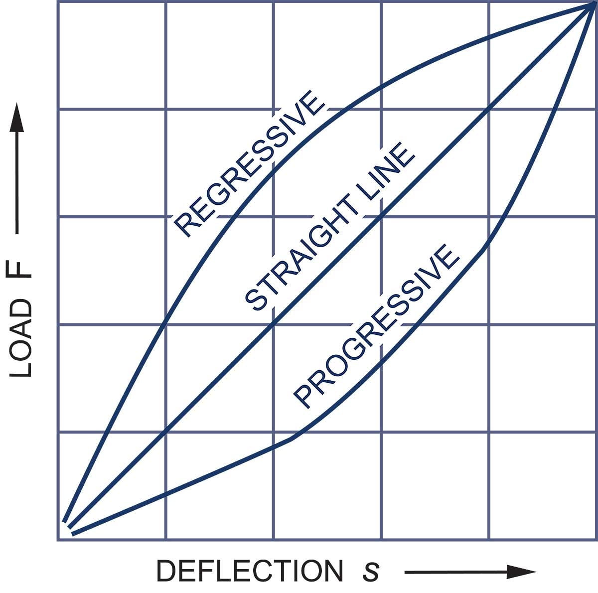
When stacking Disc Springs, a wide range of force/deflection characteristics are possible; the stack can be designed with specific load curves to meet the application requirements with both progressive and regressive possible.


April 2021

HOW TO GUIDE