ADHESIVE BONDING
By Chengcheng Sun, Ph.D. // Tongji University // Shanghai, China
By removing surface contaminants, plasma treatment can improve the bondability of CFRP.
Effects of Plasma Treatment on Bonding CFRP
Jay-Cee Sales stocks nearly 10 million pounds of fasteners at its Farmington, MI, facility, including standard small rivets from numerous vendors. Photo courtesy Jay-Cee Sales & Rivet Inc.
Thanks to their strength, corrosion resistance and formability, carbon fiber-reinforced polymers (CFRP) are increasingly being used for automotive and aerospace structures. Adhesives are ideal for assembling CFRP. Bonding does not damage or weaken the substrates. It provides high shear strength and fatigue resistance. And, it is less expensive than mechanical fastening.
However, bond strength can be compromised by mold release agents and other contaminants. For a high-strength bond, the surface must be cleaned and activated before applying the adhesive.
There are several ways to do this. Mechanical surface treatments, such as sanding or grit blasting, can damage carbon fibers and produce their own contaminants, which must be removed. Chemical surface treatments, such as acid oxidation and coupling agents, are inefficient and environmentally hazardous.
Plasma treatment does not share these drawbacks. In the past, plasma treatment had to be done in a low-pressure environment, which made the process costly. Now, however, the process can be done at atmospheric pressure, enabling the technique to be used for mass production.
We set out to understand the effect of plasma treatment on the performance of adhesive-bonded CFRP joints. We studied the effect of plasma treatment on the lap-shear strength and fracture modes of bonded joints. And, we analyzed how plasma treatment affected surface morphology, surface chemical functional groups and surface wettability.
Materials and Methods
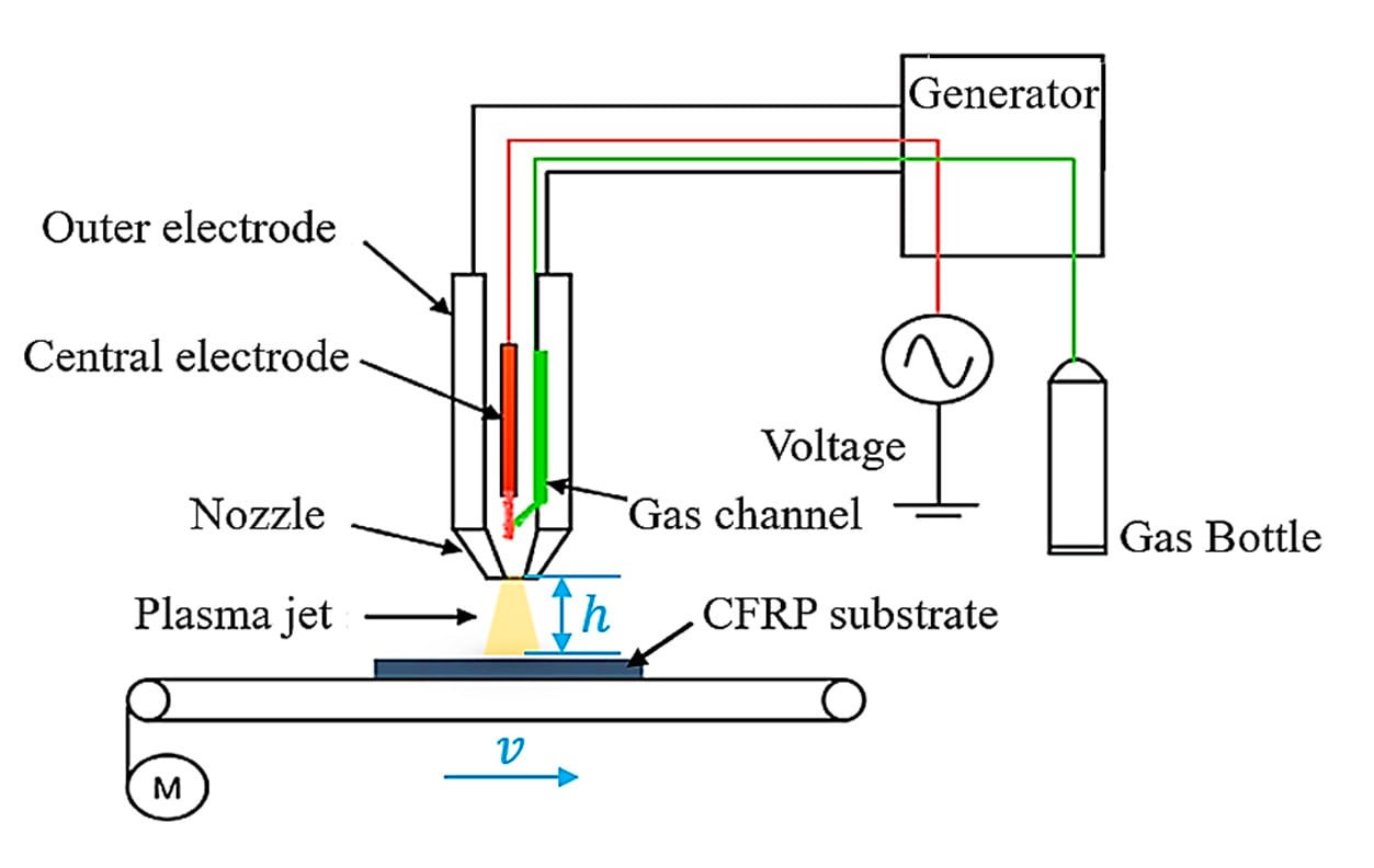
This diagram shows the setup for plasma treatment of the CFRP coupons. The key parameters of the process are nozzle height, h, and nozzle velocity, v. Illustration courtesy Tongji University
The CFRP in this study consisted of E44/51 epoxy and T300-12k pan-based carbon fibers. Carbon fiber prepregs were placed in a die coated with a release agent, dimethyl-silicon oil, and then put in an autoclave to cure for two hours at a temperature of 120 C and a pressure of 100 psi. Measuring 1.5 millimeters thick, the sheet consisted of 11 layers of prepreg. The layers were placed so that their fibers were at right angles to each other. The sheet was then cut with a water jet into coupons measuring 100 millimeters long and 25 millimeters wide.
The adhesive used to bond the tiles was 3M DP460, a two-component, room-temperature-curing epoxy.
The plasma treatment system operated at a frequency of 12 kilohertz and a voltage of 8 kilovolts. The plasma was jetted to the surface through a circular nozzle 4 millimeters in diameter. Air was used as the plasma gas, and gas flow was set to 30 liters per minute.
Plasma treatment was applied to an area 14 millimeters wide and 25 millimeters long, or slightly larger than the bond area, which measured 12.4 millimeters wide and 25 millimeters long.
The speed of the nozzle varied. Five speeds were tested: 1, 3, 5, 7 and 10 millimeters per second.
The distance between the nozzle and substrate also varied. Five distances were tested: 10, 14, 18, 22 and 26 millimeters.
Samples were named based on the speed and height of the nozzle during treatment. For example, if nozzle speed was 1 millimeter per second and nozzle height was 10 millimeters, the sample was named P1-10.
The bonding process was as follows:
Quasi-static lap-shear tensile tests were carried out to measure joint strength according to ASTM D1002-2001. A tensile tester was used to load the assemblies to failure with a cross-head speed of 10 millimeters per minute. Plates were attached to each end of the sample to minimize the effects of bending stress generated during the test. The maximum load obtained in each test was divided by the bond area to calculate the lap-shear strength of the joint.
A thermal infrared imager was used to measure substrate surface temperature during plasma treatment.
The surface morphologies of the substrates were observed with a scanning electron microscope.
The chemical composition of the substrate surface was examined using X-ray photo electron spectroscopy.
The evolution of functional groups on the substrate surface was analyzed using Fourier transform infrared spectroscopy.
To investigate the effect of plasma treatment on surface wetting, an analyzer was used to measure the contact angles of various liquids on the substrates. The liquids were deionized water, diiodomethane and ethylene glycol. Droplet volume was 2 microliters.
Differential scanning calorimetry was done to measure the chemical reaction temperature of the epoxy.
Thermogravimetric analysis was used to investigate the weight change of CFRP as temperature increases.
The bonding area of each coupon was cleaned with plasma.
Adhesive was applied to one of the coupons.
A layer of glass balls (0.25 millimeter in diameter) was scattered onto the adhesive to ensure consistent joint thickness.
Pressure was applied to remove excess adhesive from the bond area.
Joint quality was examined to ensure consistency of tensile strength tests.
The joints were cured in an oven at 40 C for two hours.
Tensile Test Results
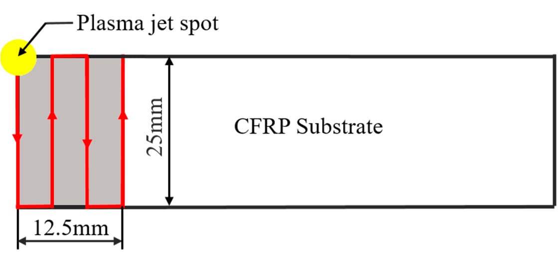
Plasma treatment was applied to an area 14 millimeters wide and 25 millimeters long, or slightly larger than the bond area, which measured 12.4 millimeters wide and 25 millimeters long. Illustration courtesy Tongji University
The lap-shear strength of bonded joints made from untreated CFRP was only 8.6 megapascals (MPa).
Among plasma-treated samples, lap-shear strength varied depending on the speed and position of the nozzle over the substrate during treatment. For example, when nozzle speed was 1 millimeter per second, lap-shear strength increased from 21.2 to 30.5 MPa as nozzle height increased from 10 to 18 millimeters. As nozzle height increased beyond 18 millimeters, lap-shear strength decreased nearly linearly.
A similar pattern was observed at faster nozzle speeds. For example, at 5 millimeters per second, lap-shear strength reached a peak value of 31.6 MPa at a nozzle height of 18 millimeters. At 10 millimeters per second, lap-shear strength increased from 27.7 to 29.7 MPa as nozzle height increased from 10 to 14 millimeters, then decreased continuously with further increases in height.
The fracture modes of the plasma-treated joints were also examined.
The fracture mode for samples P1-10, P1-14, P1-18, P5-10, P5-14, P10-10 and P10-14 was substrate failure, where a layer of broken carbon fibers was stuck on the adhesive. Therefore, the lap-shear strength was dominated by the strength of the substrate.
The fracture mode of sample P5-18 was cohesive failure. Lap-shear strength was mainly dependent on the shear strength of the adhesive, which indicates that it is not necessary to continue to activate the substrate surface, since the interfacial bonding strength between the adhesive and the substrate is higher than the shear strength of adhesive.
The fracture modes of samples P1-22, P1-26, P5-22, P5-26, P10-18, P10-22 and P10-26 were adhesive failure, similar to that of the untreated sample. In this case, the lap-shear strength of the bonded joints was dominated by the interfacial bonding strength between the adhesive and substrate.
Lap-shear strength in the case of cohesive failure was higher than that for substrate failure, which may be due to thermal damage to the CFRP from the plasma when nozzle height was too low and nozzle speed was too slow.
Temperature Results
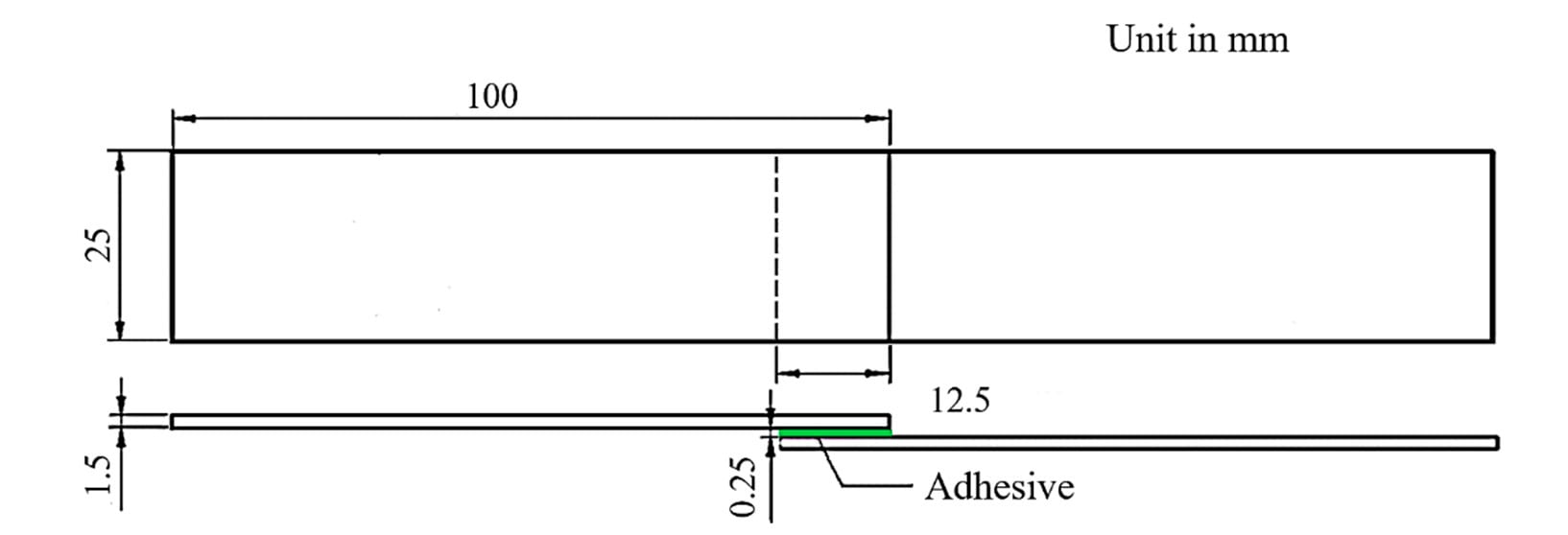
The test coupons measured 100 millimeters long and 25 millimeters wide. The bonding area is 12.5 millimeters long. Illustration courtesy Tongji University
To understand how plasma heats the substrate, we measured the surface temperature during treatment. Not surprisingly, the highest surface temperature was recorded at the shortest nozzle height and slowest nozzle speed.
Our tests found that nozzle height was more important than nozzle speed for heating the substrate. For example, when nozzle speed was 1 millimeter per second, the surface temperature decreased from 538 C to 132 C as nozzle height increased from 10 to 26 millimeters. When nozzle height was 10 millimeters, the temperature decreased from 538 C to 437 C as the nozzle speed increased from 1 to 10 millimeters per second.
The latter effect became less significant as nozzle height increased. For example, when nozzle height was 26 millimeters, the temperature decreased by only 30 C as the nozzle speed increased from 1 to 10 millimeters per second.
Surface Morphology
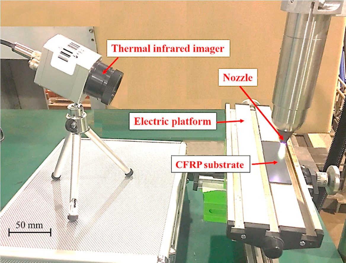
The surface temperature of the substrate during plasma treatment was measured using an infrared camera. Photo courtesy Tongji University
Scanning electron microscopy found that the surface of as-received CFRP is relatively homogeneous and smooth, but there are some tiny pores less than 2 microns in diameter on the surface of the epoxy resin.
Plasma treatment can modify the surface morphology of CFRP. For example on sample P5-10, the epoxy on the surface of the substrate was removed and the carbon fibers on the outermost layer were exposed and had minor damage. Samples P5-14 and P10-14 showed numerous pores larger than 5 microns in diameter in the epoxy.
Some scholars have reported that double bonds can be formed by eliminating water in epoxy molecules at temperatures higher than 120 C. This may enlarge the original pores on the surface or create new ones. The surface morphologies of samples P5-18 and P10-18 were nearly the same as that of the untreated samples.
Therefore, we suggest that plasma treatment will cause little thermal damage to CFRP as long as the surface temperature remains below 174 C.
Surface Chemistries
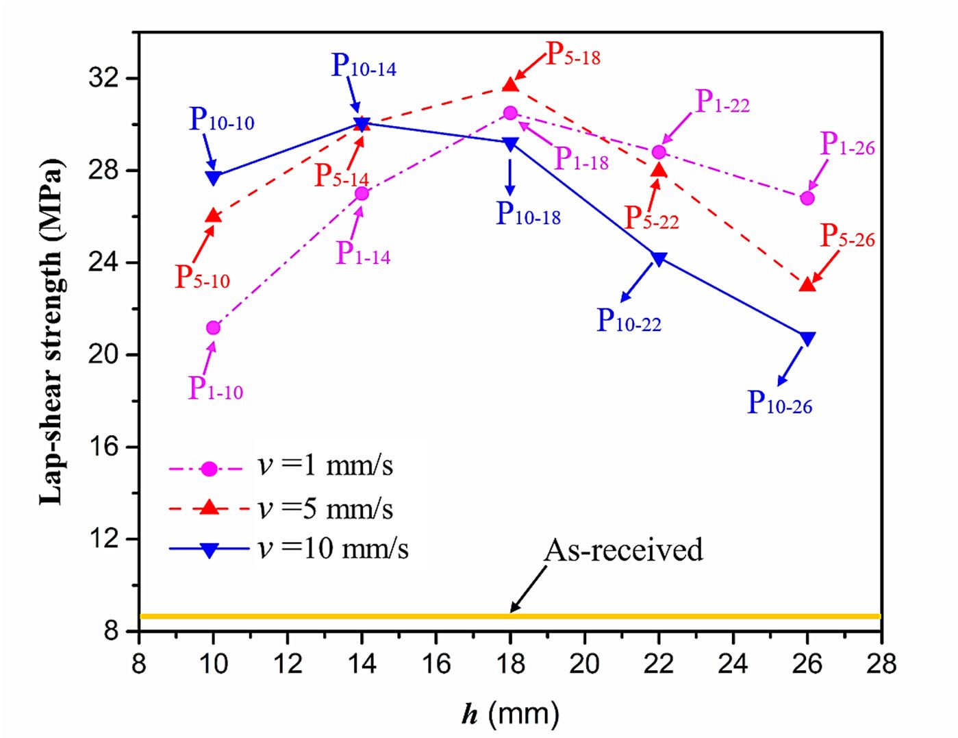
Among plasma-treated samples, lap-shear strength varied depending on the speed and position of the nozzle over the substrate during treatment. For example, when nozzle speed was 1 millimeter per second, lap-shear strength increased from 21.2 to 30.5 MPa as nozzle height increased from 10 to 18 millimeters. Illustration courtesy Tongji University
Plasma treatment can change the surface chemistry of CFRP.
For example, X-ray photoelectron spectroscopy revealed that the amount of silicon on the surface of samples P5-18, P10-18 and P5-26 was reduced by 70 percent, 51 percent and 15 percent, respectively, after treatment. Silicon is one of the components of the release agent, which blocks bonding of the adhesive to the substrate. Shorter nozzle heights and slower nozzle speeds removed more silicon than taller heights and faster speeds.
Comparing samples P5-18 and P5-26, we found that when nozzle height was increased from 18 to 26 millimeters, the amount of oxygen and nitrogen on the surface dropped by 56 percent and 45 percent, respectively. While nozzle height was fixed at 18 millimeters and nozzle speed was increased from 5 to 10 millimeters per second, the amount of oxygen and nitrogen on the surface dropped by 21 percent and 39 percent, respectively. This suggests that increasing either nozzle height or nozzle speed will reduce oxygen and nitrogen on the substrate surface.
Plasma treatment also affects carbon functional groups. For example, following treatment at a nozzle speed of 5 millimeters per second and a nozzle height of 18 millimeters, the C=O/O–C=O bond content of the CFRP increased by 118.4 percent, the C–O/C-N bond content increased by 139.5 percent, and the C–C/C–H bond content decreased by 31.7 percent.
Wettability
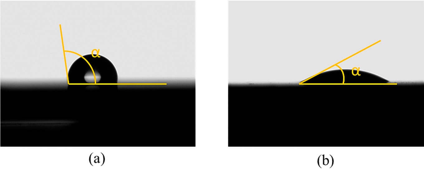
These photos show the difference in contact angles of a droplet of distilled water on untreated (left) and plasma-treated CFRP. Photo courtesy Tongji University
Plasma treatment decreased the contact angles for all test liquids. For example, when distilled water was used as the test liquid, the contact angle of as-received substrate was measured as 108.6 degrees, while the contact angle for sample P5-18 was 32.4 degrees. This indicates that the substrate surface became more hydrophilic after treatment.
To further evaluate surface wetting, we calculated the free energy of the substrate surface using the Owens-Wendt method. The free energy of sample P5-18 was calculated to be 61.33 millijoules per square millimeter—an increase of 36.81 millijoules per square millimeter over the untreated substrate.
Conclusion
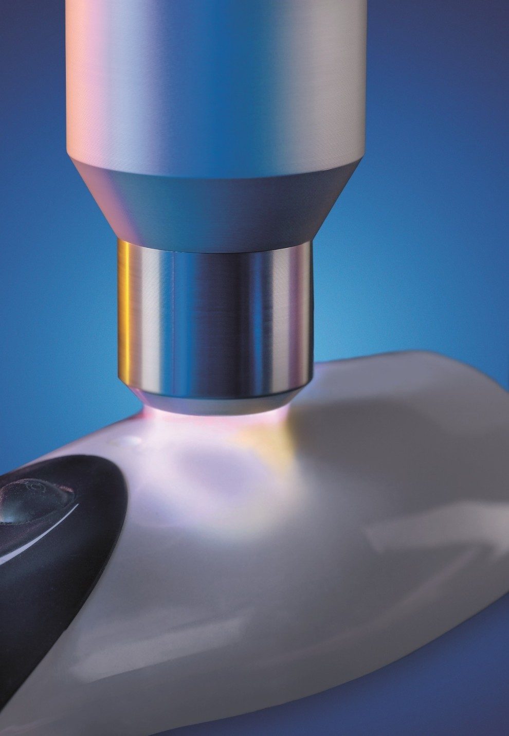
To remove surface contaminants, generate polar groups, and avoid thermal damage to CFRP, the surface temperature of the substrate should be controlled between 138 C and 175.3 C during plasma treatment. Photo courtesy Plasmatreat
To remove surface contaminants, generate polar groups, and avoid thermal damage to CFRP, the surface temperature of the substrate should be controlled between 138 C and 175.3 C during plasma treatment. When the temperature is below 138 C, favorable surface modification is not obvious. A temperature higher than 175.3 C causes the thermal damage to the substrate. The surface temperature is a function of nozzle distance and nozzle speed. Testing is required to determine the ideal combination for a specific substrate.
Editor’s note: Junying Min, Jianping Lin and Hailang Wan of Tongji University also contributed to this article.
ASSEMBLY ONLINE
For more information on adhesive bonding, visit www.assemblymag.com to read these articles:
