FACTORY OF THE FUTURE
By Jim Camillo // Senior Editor // camilloj@bnpmedia.com
Design for assembly principles can improve efficiency for manual or automated assembly.
Designing Parts
for Automation
Circular parts are quite challenging to feed, with round caps being a little easier to feed due to their thickness.
Photo courtesy Performance Feeders Inc.
That marketers increasingly use robots and automation equipment in their TV ads should come as no surprise. To them, such machinery represents the product they’re selling: An automatic and simple push-button solution to the problem consumers are worried about at that moment.
Unfortunately, they don’t tell viewers how much work goes into designing and building this technologically advanced machinery, nor do they mention the trial and error that engineers go through to ensure automated equipment accurately and consistently handles each part during assembly.
“We carefully evaluate the design of each part before we quote the price for building an automated system,” says Mike Briggs, business unit manager at ATC Automation, an integrator and machine builder since 1977. “The customer provides us with complete models and specs for the parts, including tolerances, and then we closely collaborate during the project. Our shared goal is getting the parts to go together accurately and consistently during production.”
Sometimes, though, the process does not go smoothly. Briggs recalls a project ATC undertook with a manufacturer, and repeat customer, that makes hydraulic motors for lawnmowers and excavators.
“They wanted us to build a single automated assembly line for several different motors, each of which had been built on a manual production line,” notes Briggs. “After extensive research, we had to tell the company not all motor models could be built on one line. It required two assembly lines to prevent overloading the line and creating inefficiency.”
The reason for multiple lines, according to Briggs, was that not all motors could use the same housing. As a result, problems arose when trying to configure all the parts in the same way within different housings. One model became too top heavy, and another was unable to be properly mounted to the excavator.
“We ended up building a high-volume line for most of the models and a low-volume line for the others,” explains Briggs. “Each line took 10 to 11 months to build, and utilizes the Bosch TS pallet-transfer system with an elevator on both sides and a return conveyor underneath.”
Designing parts for automated assembly has always been a challenge for engineers. This is especially true when automating a process that was previously done manually. What’s easy for a person to do is rarely simple for a robot, which is not blessed with human sight, touch or dexterity. And, whereas people can compensate for minor irregularities in parts, a robot can only perform the same programmed routine time and again. If two parts do not fit as expected, the robot cannot finesse them together. It will simply pass the faulty assembly to the next station.
To maximize the efficiency and reliability of automated assembly systems, engineers must design parts specifically to be handled and fed by robots, vibratory bowls and other automated equipment. A screw with a cone point or oval point is easier to install with an automatic driver than a screw with a standard rolled-thread point. Closed-ended springs and washers are easier to feed than those with open ends. Adding a rib, shoulder or indentation to a plastic part can make a world of difference in how easy it is to feed and grip. Adding a chamfer to a hole can make inserting a part much easier.
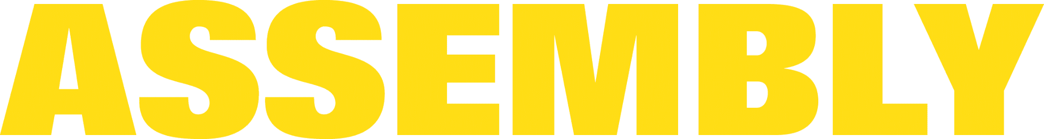
DFMA Still Leads the Way
This graphic illustrates how parts change when designed according to DFMA principles. The revised parts are on the right. Graphics courtesy Medntechnology.co.uk and Steiner Technologies
The basic principles of design for manufacture and assembly (DFMA) are a good place to start, regardless of how the product will be assembled. DFMA is a technique pioneered by University of Massachusetts professor Geoffrey Boothroyd and University of Manchester professor Peter Dewhurst in the 1980s. It combines DFM (design for manufacturing) and DFA (design for assembly), and is used throughout the entire product development lifecycle—from concept selection to cost estimating and product benchmarking.
DFM focuses on minimizing part cost though choosing the best manufacturing process, the optimal material and the best tool for making the product. DFA emphasizes minimizing the total cost of the product by reducing total part count, assembly time and the complexity of the assembly process.
“DFMA rules are proven and easy to understand,” says David Meeker, founder of Neoteric Product Development, a consulting firm. “Rules related to automation-based design techniques, like design for automation, are minimally different, and often apply only to specific processes like parts feeding.
“In general, nine out of 10 products designed using DFMA can be made just as well manually as with automation, although DFMA will improve the automated assembly process,” continues Meeker. “It’s really a question of having the necessary labor to make the products at the desired volume.”
Minimizing parts is the biggest advantage of the DFMA methodology, but other basic tenets must not be overlooked, according to Meeker. Engineers should design products that require few or no fasteners and no reorientation during assembly. Modular design is also recommended if making a family of products with feature variations.
Meeker says all disciplines involved with product design and assembly need to be on the same page technique-wise, for a project to be completed smoothly and on time. He acknowledges the likelihood that the design engineer, equipment suppliers and integrator may not all follow DFMA to the same degree. In that instance, the goal is to emphasize DFMA at the level possible to create a successful product.
At ATC, engineers advise customers to incorporate DMFA principles into their designs to optimize part handling. This is important to do as early as possible in the design stage. A rule of thumb is that 70 to 80 percent of a product’s cost is determined at the design stage.
“More than anything, the focus of design for automation is making sure that each part is processed as efficiently as possible,” says Aaron Donlon, product manager at Epson Robots. “This requires the engineer to understand which downstream equipment will handle the part, as well as when, how and for how long.”
Keep it Moving
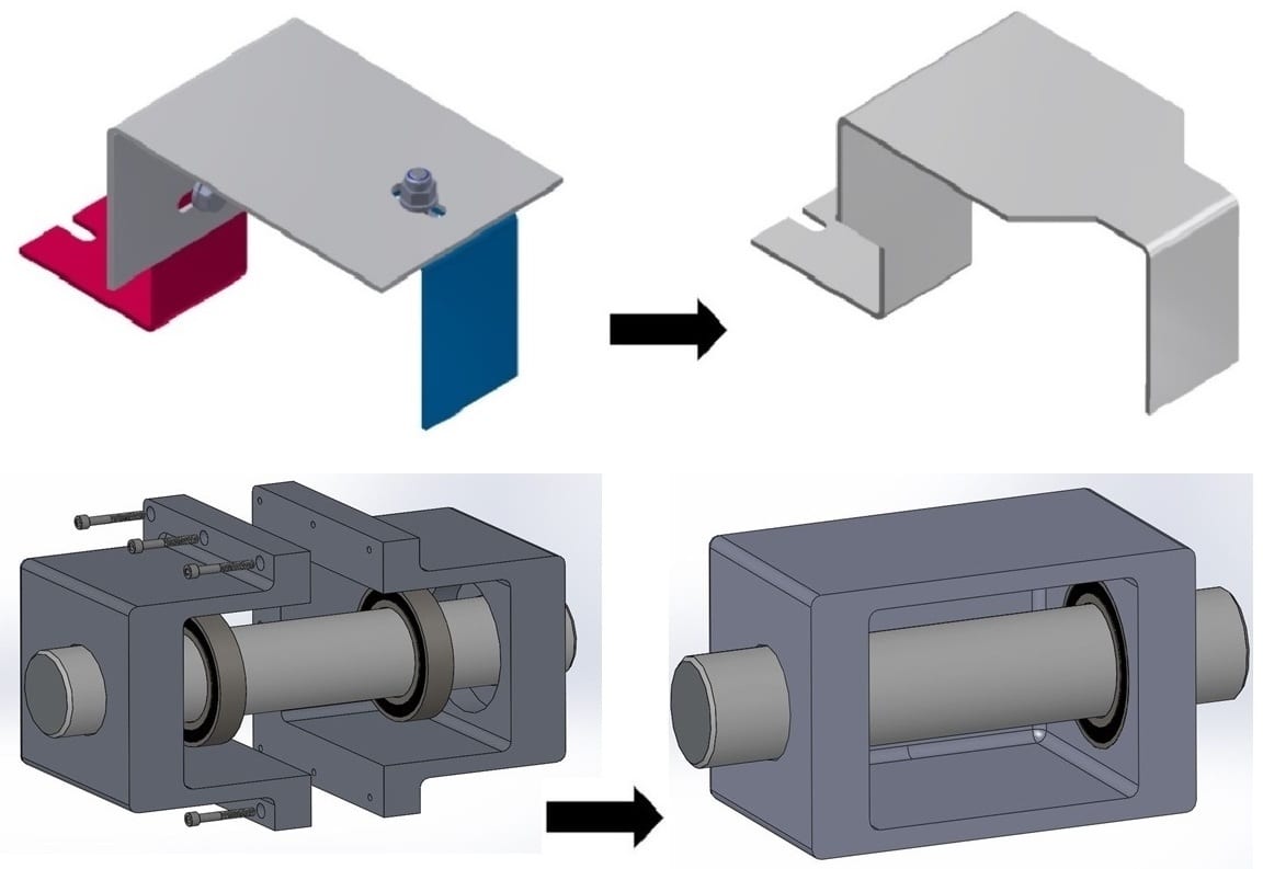
DFMA emphasizes the importance and benefits of symmetry in part design. Graphic courtesy Christoph Roser at AllAboutLean.com
On an automated production line, parts make one or more stops at workstations on their way to being assembled into a final product. How the parts are initially fed can have a big impact on how smoothly, efficiently and consistently they get assembled along the way.
“Parts with no tabs or external protrusions at all are the hardest to orient,” claims Greg Pflum, CEO and president of Performance Feeders Inc. “Parts need to press against each other a bit to create a little backlog for them to be properly conveyed. If this doesn’t happen, the parts may just overlap and jam the inline, conveyor or gravity track.
“Component material is not the issue, as this guideline applies to plastic and metal parts,” Pflum continues. “Rather, it’s the geometry and consistency of the parts. Without both, parts can’t be efficiently fed.”
The best parts to feed, according to Pflum, are those with one or more right or parallel angles. This shape makes it easy to convey or grab the part, regardless of its orientation.
“Circular parts, like washers, can be quite challenging to feed,” says Pflum. “When they are thinner than 0.005 inch, they tend to stack on top of each other and won’t feed up the feeder bowl. When they are less than 0.03 thick, they are subject to jamming in the inline.
“Round caps are a little easier to feed due to their thickness, but their feed rate will be different in vibratory and centrifugal systems,” he continues. “For example, a 1.5-inch-diameter cap can be fed at a rate of 60 to 120 parts per minute in a vibratory bowl or step feeder, vs. 900 parts per minute in a centrifugal system. Centrifugal feeders are designed more for high-speed feeding.”
In his experience, Briggs says cylindrical parts are the easiest to feed and convey, especially if they have a small external feature or two that enhances location by a robot or vision system. Upside-down parts are usually hard to feed, as well as those without a reasonable amount of mass in their center.
“Proper spacing and singulation always improves part feeding,” notes Marco Micheletti, automation director at Fresh Consulting. “Our engineers have found that using a lift or hoist elevator with the bowl feeder helps achieve both goals.”
As they move along the assembly line, parts get handled by automation equipment or a robot. Ideally, the parts will be clean and repeatable in shape and size when presented to the robot. Debris-covered and multi-shaped parts are never easy to pick up, which could result in the robot either dropping the part or bypassing it altogether to maintain its preprogrammed cycle time.
“Large parts or products do sometimes require more robot handling time,” says Donlon. “Recently, a large manufacturer customer noticed that a robot with a vacuum cup often failed to cleanly grab and move plastic packages. Using a high-speed camera enabled us to determine why this was happening: The cup’s evacuation time was too short. Extending it slightly, from 200 milliseconds to 300 milliseconds, enabled the cup to stay on the package, rather than roll off. Equally important, productivity wasn’t impacted, staying at 60 parts per minute.”
Machine-guided vision can be a huge advantage for robotic parts handling, according to Donlon. He also says that backlighting is more reliable than top lighting in a factory environment. Another recommendation he offers engineers is to use parts with durable surfaces or coatings (like ceramic) that aren’t easily damaged by gripping.
“Too often, engineers rely too much on their equations and calculations when designing parts rather than performing function testing of the actual parts themselves,” says Briggs. “We saw this happen amongst mechanical engineers for an automotive manufacturer that needed to design a hydraulic valve. Their calculations showed a 100 percent accurate fitting of pins within the bushings, and that their insertion required just 350 pounds of force.
“However, testing showed that the pins actually needed 10 times that amount of pressure, 3,500 pounds, to be inserted,” continues Briggs. “As a result, we had to replace the planned pneumatic actuator with a much larger electric one that cost $600,000 more. Not surprisingly, the project was one of the first for them in making this type of product.”
In the late 1980s, IBM decided to design its Proprinter for automation. The printer was intended to complement IBM’s growing personal computer business, according to Meeker.
“What they discovered is that when one designs for automation, one also designs for manufacturability,” notes Meeker. “The design for automation lead to dramatic reduction in fasteners, assembly time (170 seconds), and parts and subassemblies (32). The product automation was successful in part because the Proprinter had reached its theoretical minimum part count.”
A Fresh Approach
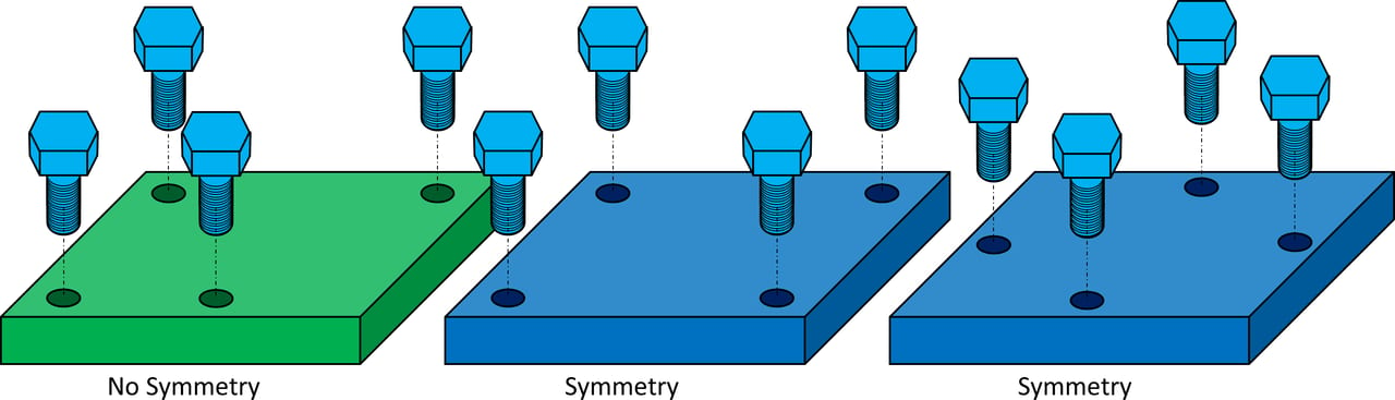
Since 2019, Fresh Consulting has implemented the use of automation and robots to help its clients with their product assembly and testing (shown here). Photo courtesy Fresh Consulting
Based in Seattle, Fresh Consulting is a full-service product development company that was founded in 2007. Since 2019, the company has implemented the use of automation and robots to help its clients with their product assembly and testing. Clients range from Fortune 500 OEMs, to logistics companies, to small entrepreneur-inventors, and growing mom-and-pop manufacturers with a niche product they want to assemble with automation.
“Understanding market fundamentals plays a significant role in determining whether or not a company should automate assembly,” opines Micheletti. “Knowing the product’s intended lifespan and expected production volume are also key factors in determining the ROI of any automation capital investment.”
When a prospective client meets with Fresh engineers, the client discusses its automation goals and preferred equipment. These include feeders, conveyors, robots, indexers, motors, vision systems, sensors, gearboxes and PLCs.
“The process that they choose to assemble their parts is always crucial,” says Micheletti. “If they pick the wrong process for a specific application, they’ll likely pick the wrong equipment, negatively impacting how the parts are fed, handled and joined together. When the client is committed to using automation, we examine the process in light of their assumptions related to cycle time, production rate and other factors.
“Together we determine what makes sense for a reasonable ROI, and then we focus on the most opportunistic aspects of the assembly process to achieve it with automation,” adds Micheletti. “It has happened where the best approach is building a simple workcell in which a handful of assembly processes take place.”
One example he cites involved the customer transitioning from a simple manual assembly process involving the soldering of two parts, to an automated workstation where the parts are fed to a location and soldered together. The client was made aware that, because part tolerances are much tighter in the latter case, so is the margin of error.
“Using automation to join parts does not mean they can simply be shoved into the right spot as needed,” explains Micheletti. “We believe in smartly designed parts, but not overly designed ones. When precise orientation is needed, a vision or active alignment system can ensure that only parts in tolerance get processed.”
Micheletti and other design engineers at Fresh do follow DFMA principles—to the degree that each project allows. He cites the opportunity to use a part for multiple functions in the product design and assembly. Although sometimes it might make sense to redesign the multifunction part into two parts to simplify production.
“Never automate an assembly process until all the design bugs are worked out for the product and you have the right key performance indicators in place,” says Micheletti. “All automation steps must work equally well for optimum parts feeding, handling and assembly. Also be sure to build in as much flexibility as possible.”
Regardless of the client, Micheletti and his designers recommend that it always have a backup plan for automating complex processes, just in case. He points out that, regardless of how well thought out, designed, engineered and executed each workstation and assembly process may be, sometimes challenging complex automation processes may not achieve the desired operational efficiency requirements.
“This plan may entail including extra space in a station for duplicate or additional operations or finding locations for offloading parts to a manual station,” concludes Micheletti. “It may even mean just starting with a manual process until you encounter any technical challenges.”
ASSEMBLY ONLINE
For more information on DFMA, visit www.assemblymag.com to read these articles:
Product Design: Design First, Lean Second.
Think Inside the Box: Design for Manufacturing and Assembly.
FACTORY OF THE FUTURE MARCH 2022