

July 2023

MOTION CONTROL
Comparing Position Sensors for Cylinder Feedback
To measure the position of a piston rod, engineers have a choice of three technologies.
Labor shortages are driving new demand for automation.
Options for Screwfeeding
Labor shortages are driving new demand for automation.
Options for Screwfeeding
This variable inductance sensor is mounted to an actuator for a rocket launch system. Photo courtesy Alliance Sensors Group
Comparing Position Sensors for Cylinder Feedback
To measure the position of a piston rod, engineers have a choice of three main technologies.
Ag Equipment Maker Reaps Benefits of Cranes
Cranes and hoists help assemblers position heavy loads safely, precisely and efficiently.
DC-Pro chain hoists are used to raise and lower parts. These units have load capacities of up to 1,000 kilograms when moved by hand and up to 2,000 kilograms when moved electrically. Photo courtesy Demag Cranes & Components GmbH
Edward E. Herceg // Chief Technology Officer // Alliance Sensors Group // Moorestown, NJ
Position feedback sensors for hydraulic or pneumatic cylinders have traditionally used one of three technologies: magnetostrictive, variable resistance and variable inductance sensors.
While other sensor technologies have occasionally been used successfully in this application, this article will focus solely on the three most popular technologies. As demand for greater control and functionality has increased, sensor-instrumented cylinders are becoming more important in the heavy industry, subsea and mobile equipment worlds. Ultimately, a user or systems integrator must determine the requirements of the application and which technology best satisfies those requirements on a total installed cost vs. performance basis. This article will compare the strengths and weaknesses of magnetostrictive, variable resistance and variable inductance sensors.
Initially, a point to be noted is that all of these common sensing technologies use a long probe that extends into a deep, small diameter blind hole that has been gun-drilled into the internal end of the cylinder rod.

Magnetostrictive
Magnetostrictive technology has been the preferred technology for high-accuracy applications. The sensor, often called a linear displacement transducer or magnetostrictive linear displacement transducer, incorporates a stainless steel tubular probe and a short toroidal permanent magnet assembly around it that is installed in a counterbore in the piston.
The most common package is designed to thread the sensor’s electronics housing into an O-ring port in the back of a cylinder, with the long slender probe inserted into the rod’s bore. It uses the “time of flight" principle to determine the magnet’s position with high accuracy and moderate response time. The magnet is used to reflect a torsional mechanical pulse that is transmitted along a special wire inside of the probe called a waveguide.
Typically, each manufacturer of magnetostrictive sensors has its own style of magnet with unique mounting features, such as the number and pattern of the holes. Magnetostrictive sensors can consume a fair amount of power and are not the most mechanically rugged sensors. They offer electrical performance over mechanical robustness, because they are subject to shock and vibration issues. Yet, while there are some potential drawbacks mechanically, the magnetostrictive sensor’s package design is tailor-made for port-mounted in-cylinder use.
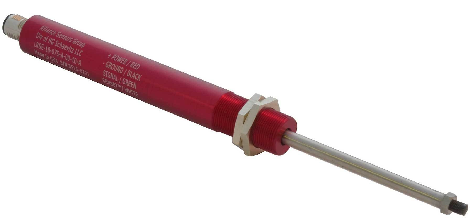
Variable inductance position sensors have significant advantages over resistance potentiometers in terms of product life and long-term reliability. Photo courtesy Alliance Sensors Group
Variable inductance position sensors compete favorably with magnetostrictive sensors in terms of linearity, resolution, and frequency response. Photo courtesy Alliance Sensors Group
Variable Resistance
Variable resistance potentiometer-type sensors, commonly called pots, are selected where purchase cost is a driver and high accuracy is not paramount.
A resistance pot is usually embedded into the cylinder’s rear end plate, as opposed to the port mounting of magnetostrictive sensors. It uses an insulated round carrier that is attached to the internal end of the gun-drilled cylinder rod and supports an electrically conductive wiper that contacts the surface of a partially conductive plastic probe. As the wiper moves along this plastic element, its resistance changes in a linear fashion, making it fairly easy to determine the carrier’s position and, thus, the rod’s position.
Pots have been seen as a good position measurement sensor for cylinders because of their ruggedness, favorable stroke-to-length ratio, and their large analog DC voltage output, which is a big percentage of the input voltage. The major drawback to resistance pots is durability, especially if the cylinder is actuated at a high frequency, or even more importantly, dithered over a short range to improve a system’s dynamic characteristics. Since a resistance pot is embedded into the cylinder, replacement of a worn-out pot can be time consuming and expensive. It could even result in the need for a completely new cylinder.
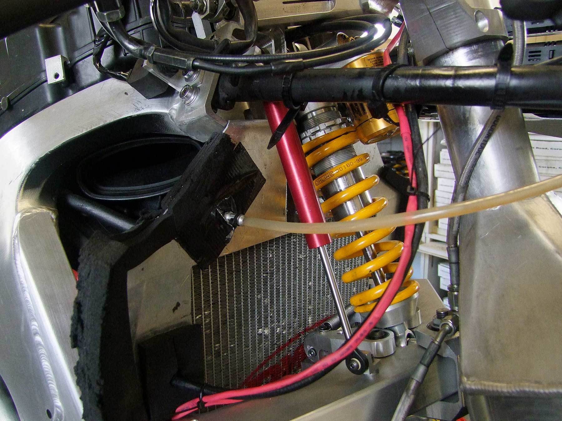
Variable inductance sensors can withstand much greater shocks and vibration. Here, a sensor is mounted to a vehicle suspension system. Photo courtesy Alliance Sensors Group
Variable Inductance
XXX
AdCreative Missing.
(double-click to add)
xxx
xxx
xxx
xxx
- xxx
- xxx
- xxx
Editor’s note: xxx

xxx
Variable inductance position sensors have been used in the cylinder industry, but have not had the widespread recognition of magnetostrictive sensors or resistance potentiometers. This noncontact technology has significant advantages over resistance potentiometers in terms of product life and long-term reliability. They usually compete favorably with magnetostrictive sensors in terms of linearity, resolution, and frequency response, but at a significantly lower cost. Equally important is the fact that variable inductance sensors can withstand much greater shocks and vibration, such as those commonly found in heavy industrial and mobile equipment applications.
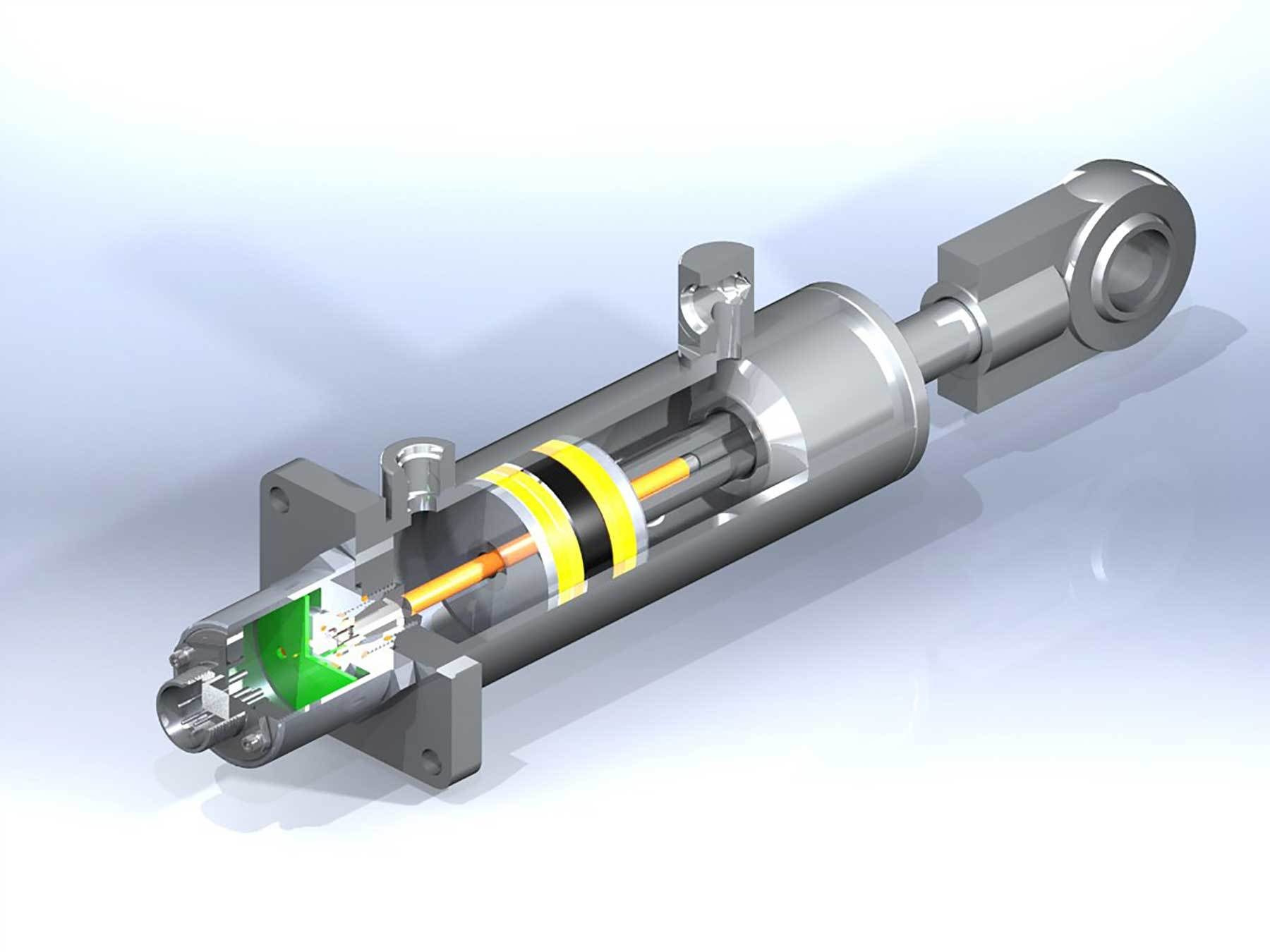
Linear variable inductance sensors cover the middle ground between the higher level of performance and external port mounting flexibility associated with a magnetostrictive sensor and the ruggedness and price of an embedded resistance potentiometer. These sensors operate by measuring the resonant frequency of an oscillator circuit that uses an inductive probe whose inductance is varied by the position of the gun-drilled rod over it.
Typically offered in full scale ranges of 4 to 36 inches, both port-mounted and embedded packages are available, with connector and cable terminations that match those found on most catalog magnetostrictive sensors. These sensors offer either an analog DC voltage or current output, with an SSI digital output available for OEM applications. The variable inductance sensor is a noncontact device that does not require a ring magnet. In fact, if a variable inductance sensor were installed to replace an existing magnetostrictive sensor, the magnet can be left in place in the cylinder rod end without interfering with the sensor’s basic operation.
In the past few years, the requirements for instrumented cylinders for subsea applications have dramatically increased. Variable inductance sensors can be offered in a pressure-sealed version that allows a user to install the sensor-and-cylinder in a subsea environment in depths of 10,000 feet with 3,000 psig of internal hydraulic pressure.
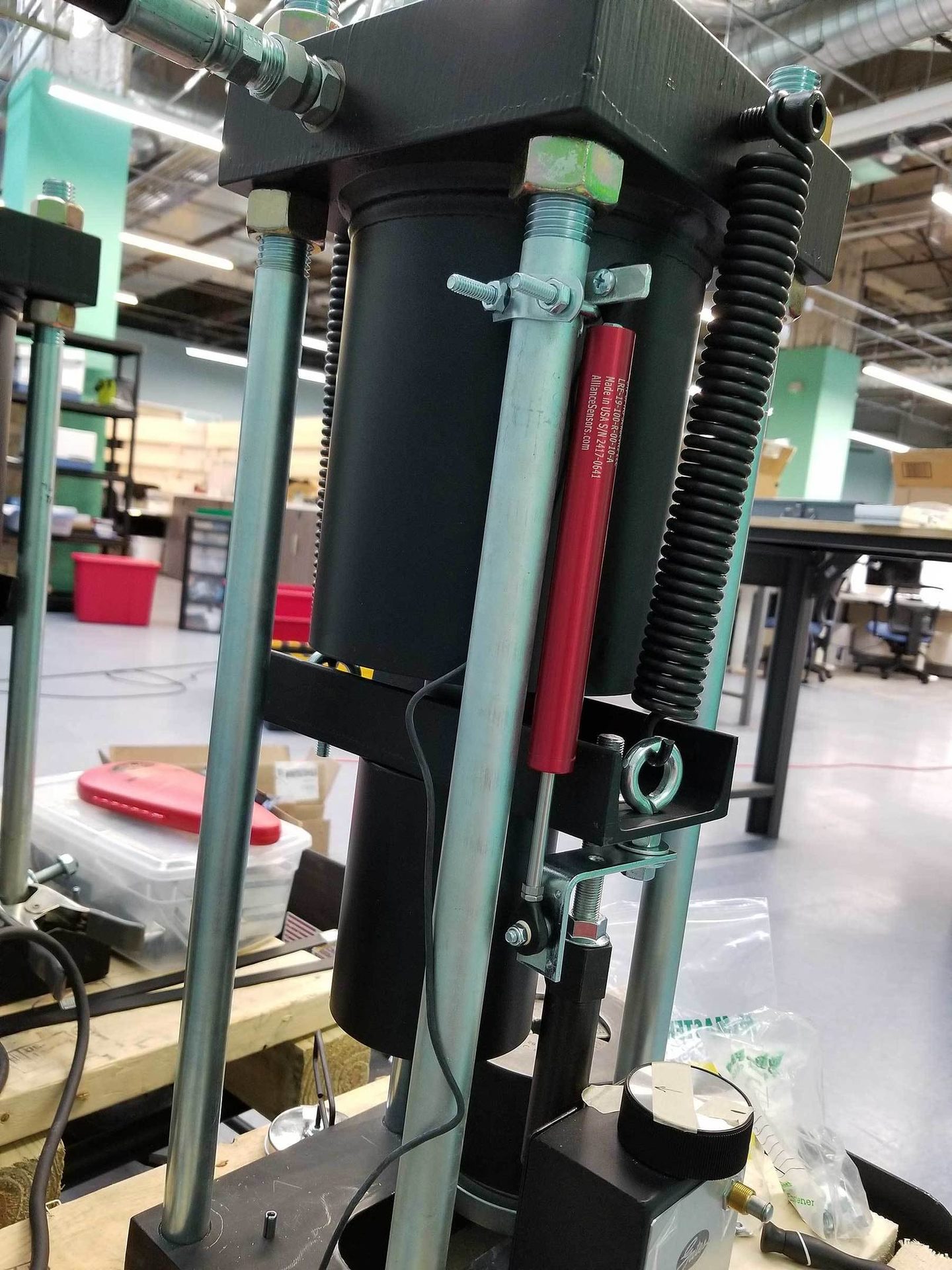
This variable inductance sensor measures the position of the ram on a crimping press. Photo courtesy Alliance Sensors Group
Remote field calibration is a standard feature offered on many variable inductance sensors. This feature permits a user to scale the output of the sensor while it is being installed on the cylinder. With a push of a button to set the zero and the full-scale output points, the sensor will give the desired full-scale output over its newly set range, so it is no longer necessary to scale the unit in an operating control system.
In another fluid power application, though not commonly used inside of hydraulic cylinders, LVDTs are often used in spool position feedback applications for two-stage hydraulic valves. A short range variable inductance sensor with its simple inductive probe inserted into a hole in the end of the main spool is often an easier installation than an LVDT that requires an isolation tube to seal off the its core from the valve’s pilot pressure.
While there are still many fluid power applications where resistance potentiometers and magnetostrictive sensors are good choices, these applications tend to fall to either side of a bell curve. Recent electronic advancements and the flexibility of package designs make variable inductance sensors cost-effective for mainstream in-cylinder applications that tend to be near the peak of that bell curve.
ASSEMBLY ONLINE
For more information on position sensors, visit www.assemblymag.com to read these articles: