
MONTH 2023

Adhesives and Dispensing
Photo: Maximusnd via iStock / Getty Images Plus
The right joint design can mitigate damage to bonded assemblies caused by high-speed impacts.
High-Velocity Impacts
How Do
Affect Adhesive Bonding?
Labor shortages are driving new demand for automation.
Options for Screwfeeding
Photo: Maximusnd via iStock / Getty Images Plus
The right joint design can mitigate damage to bonded assemblies caused by high-speed impacts.
High-Velocity Impacts
How Do
Affect Adhesive Bonding?
Ferhat Kadioglu, Ph.D. // Professor // Department of Aerospace Engineering // Ankara Yildirim Beyazit University // Ankara, Turkey
While many studies have examined the behavior of adhesive bonds under qua-si-static and fatigue loading conditions, research focused on their response to impact loading is scarce. This gap is noteworthy because, in service, bonded joints are often exposed to sudden or unexpected high-rate events, such as tool drops during maintenance, debris impact during flight or driving, and even crash scenarios.
The lack of sufficient understanding of adhesive joint performance under such dynamic conditions can hinder their broader adoption in critical load-bearing applications, especially where crashworthiness or damage tolerance is para-mount. Furthermore, dynamic events often involve a combination of high strain rates, rapid stress wave propagation, and complex failure mechanisms, making it essential to investigate these phenomena beyond traditional quasi-static approaches.
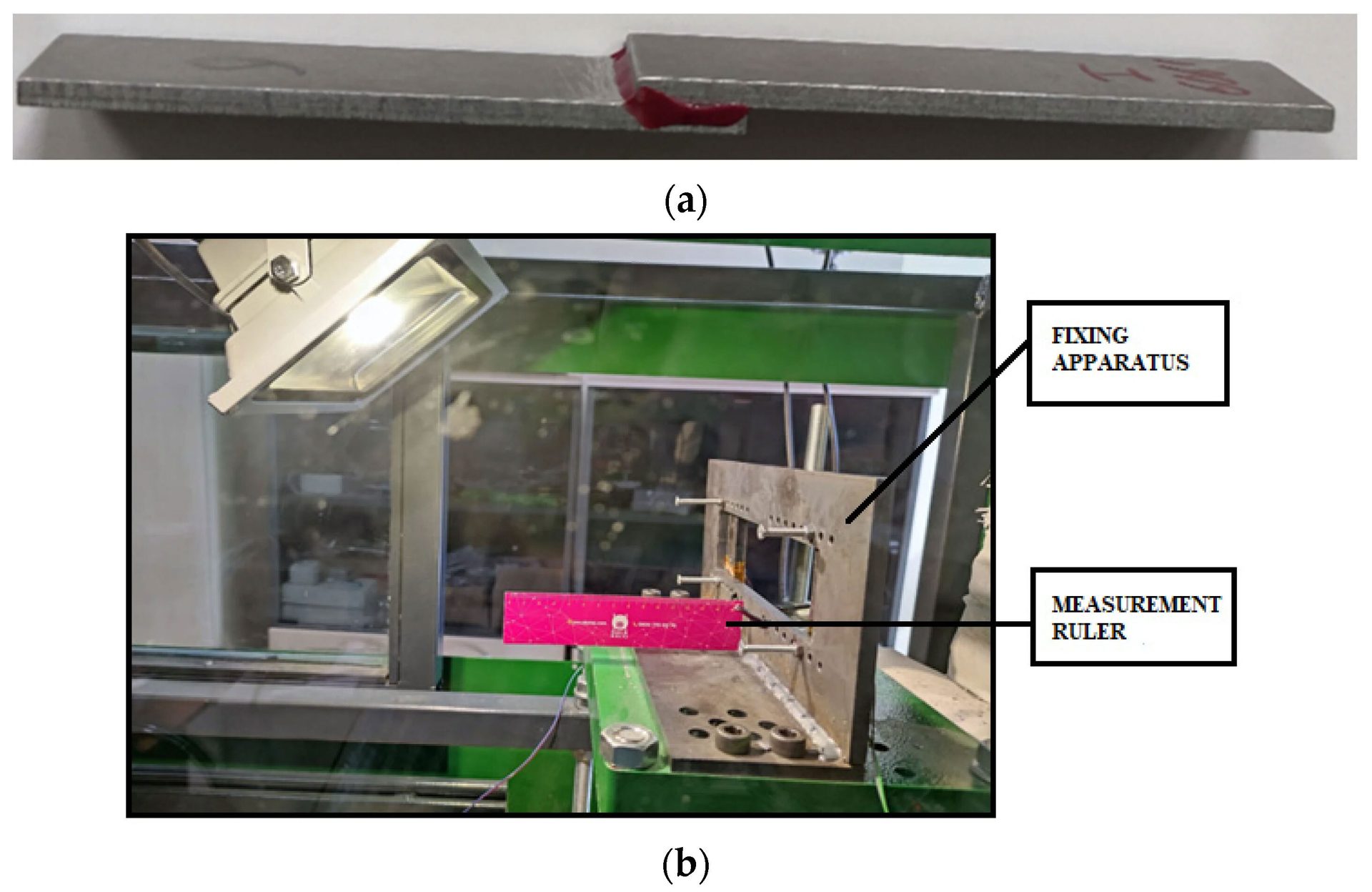
These images show the bonded test coupons (a) and the apparatus (b) in which the specimens are fixed before the test. Source: Ankara Yildirim Beyazit University
Structural adhesives exhibit optimal load-bearing behavior under shear-dominated conditions. One key difference between impact and quasi-static loading is the increase in yield strength with higher strain rates. This phenome-non is well-documented in metals, but equally relevant in adhesives, where molecular mobility becomes restricted at high deformation speeds, leading to an apparent stiffening effect. However, beyond a threshold strain rate, this yield strength enhancement tends to plateau.
Incorporating Z-pins, or reinforcing fibers, into single-lap adhesive joints can enhance their post-impact load-bearing capacity and energy absorption com-pared with conventional joints. The improved residual strength comes from the hybrid joint’s ability to distribute and absorb impact energy, reducing delami-nation and improving structural integrity after impact.
The most common methods to test bonded joints at elevated loading rates are pendulum impact devices, drop weight testers, and Split Hopkinson pressure bar systems. These setups are generally effective for moderate-speed impacts, typically under 10 meters per second (m/s) for drop tests and about 5 m/s for pendulums.
However, structural adhesive joints in real-world applications may encounter much higher loading rates due to blast waves, high-speed debris, bird impacts, or collisions with moving objects. The challenge is further compounded by the fact that experimental replication of such extreme scenarios is complex, often requiring specialized high-speed equipment and robust safety measures. Conse-quently, research into ballistic or near-ballistic loading of adhesive joints has been limited.
This lack of empirical data represents a barrier for industries that want to use adhesives in safety-critical structures exposed to potential high-velocity im-pacts. Without such data, predictive modeling of joint survivability under real-istic accident or threat scenarios remains uncertain.
We set out to address this knowledge gap. Our study explores the dynamic response of SLJs subjected to high-strain-rate loading. A custom-designed ballistic apparatus was employed to subject SLJs to impact from a lead projectile at a velocity of 288 m/s. Our test joints consisted of two identical aluminum coupons. Each coupon was 3, 4 or 5 millimeters thick. The overlap lengths was either 15 or 25 millimeters.

The damaged joints were subsequently characterized through quasi-static tensile tests to assess their residual load-bearing capacity. To gain a deeper understand-ing of the mechanical degradation, the impacted joints were compared with non-impacted specimens.
Complementary to the experiments, we performed detailed finite element (FE) simulations using ABAQUS 2021. We employed the Johnson-Cook material model to describe the plastic behavior of the metallic adherends and projectile, while the adhesive layer was represented using a cohesive zone model, enabling comprehensive analysis of damage initiation and propagation. This dual exper-imental-numerical approach provides a rare, holistic view of bonded joint per-formance under ballistic loading, bridging the critical gap between laboratory testing and real-world service demands.
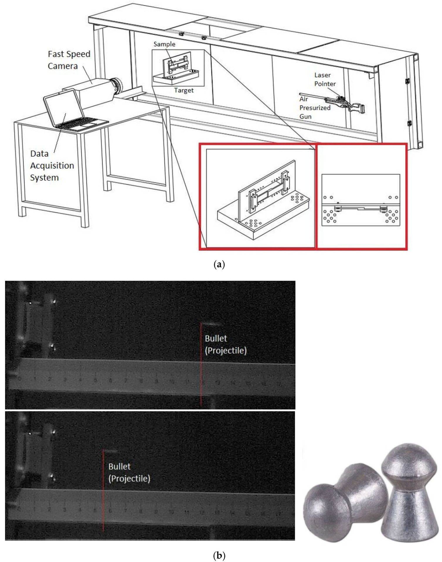
The test setup (a) consisted of a pressurized air gun, a high-speed imaging system, data acquisition equipment, and a custom clamping fixture to securely hold the test specimens. A high-speed camera captured the bullet in flight (b). Source: Ankara Yildirim Beyazit University
Experimental Work
The SLJs were made from 6061 aluminum alloy bonded with a modified epoxy film adhesive. The coupons were sanded and cleaned prior to bonding. The bonding process was conducted in a digitally controlled oven at 125 C under a pressure of 2 bars for one hour, in line with the manufacturer’s guidelines.
The test setup consisted of a pressurized air gun, a high-speed imaging system, data acquisition equipment, and a custom clamping fixture to securely hold the test specimens. Measuring 5.5 millimeters in diameter, the projectiles were round-nosed lead pellets, each weighing 1.25 grams. The distance from the projectile to the target was 210 centimeters.
After impact, the joints were subjected to quasi-static tensile loading using a universal testing machine with a maximum load capacity of 100 kilonewtons. To assess the extent of performance degradation, the results obtained from the impacted joints were compared to those from pristine, unimpacted specimens.
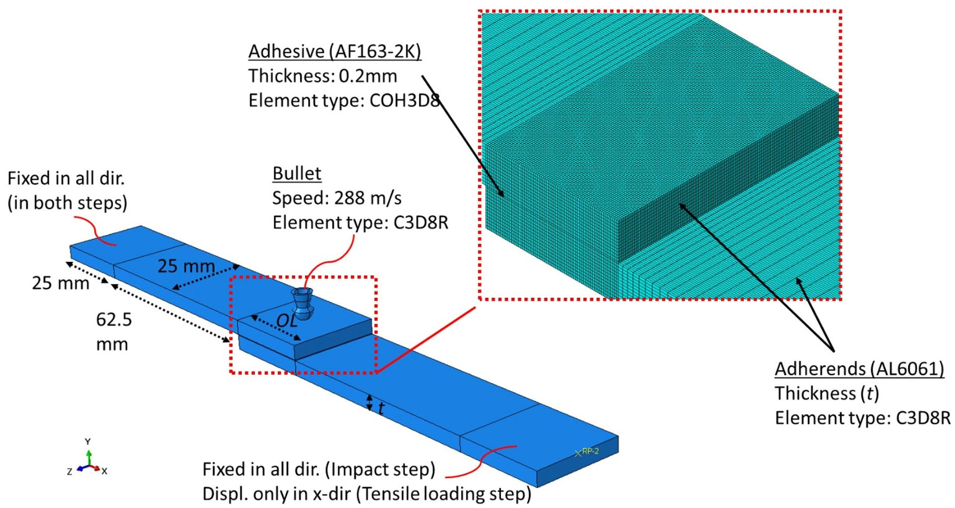
This illustration shows the 3D finite element model of the lap joint subjected to a high-speed impact followed by quasi-static tensile loading. Source: Ankara Yildirim Beyazit University
Numerical Modeling
Numerical analyses were conducted using ABAQUS to investigate the dynamic response of SLJs under impact conditions. We developed a detailed 3D FE model. The aluminum coupons were represented by eight-node linear brick elements incorporating reduced integration and hourglass control to improve both computational efficiency and numerical stability.
To ensure accurate prediction of stress concentration and progressive damage, a highly refined mesh was applied in the overlap zone, featuring element dimensions of roughly 150 by 150 by 150 microns for the adherends and slightly coarser elements of 150 by 200 by 150 microns for the adhesive layer, resulting in approximately 16,666 elements within the adhesive for an overlap length of 15 millimeters.
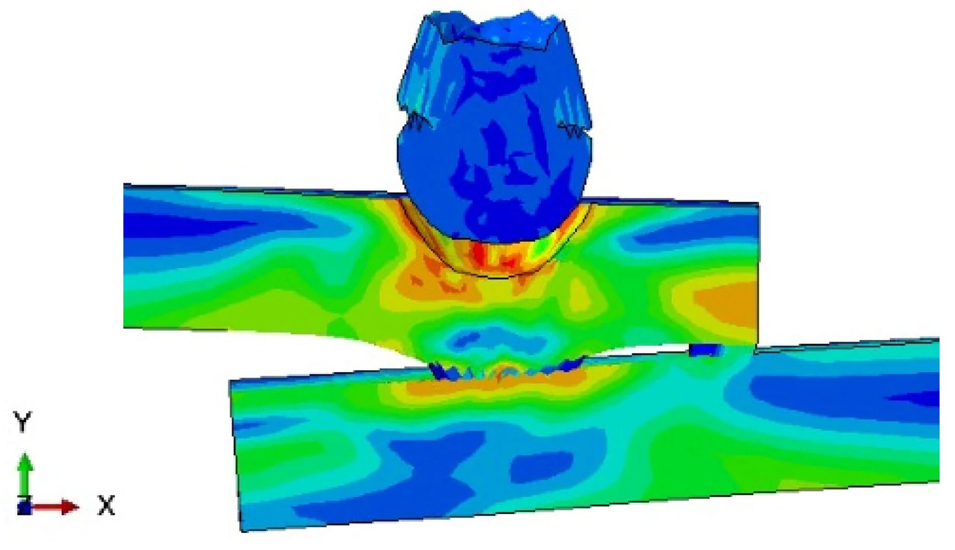
This simulation image shows the deformed shape of the SLJ six microseconds after the bullet impact. Source: Ankara Yildirim Beyazit University
Beyond the overlap region, a graded mesh with a bias ratio of 2 along the joint length was employed for the coupons. Mesh convergence was validated by comparing the predicted force-displacement curves, which exhibited deviations of less than 5 percent relative to results obtained from finer mesh. This mesh configuration was also examined for the damaged area after the impact test, and the difference compared to a finer mesh was found to be less than 3 per-cent.
The adhesive layer—generated by separating the overlap section from the ad-herends—was simulated using linear cohesive elements.
The simulation procedure was carried out in two consecutive stages. In the first stage, the SLJ was impacted by a deformable projectile modeled with solid el-ements and assigned an initial velocity of 288 m/s.
This simulation image shows the change in the distributions of von Mises stress on the bonded joint 4 microseconds after high-speed impact with the bullet. Source: Ankara Yildirim Beyazit University
The second stage simulated the tensile loading of the deformed configuration obtained from the preceding analysis. During both stages, one end of the SLJ was fully constrained in all degrees of freedom, whereas the opposite end remained fixed during the impact phase and was subsequently released to allow axial displacement in the tensile loading step.
To model the coupons and the projectile, the Johnson-Cook material model was employed, since it is widely recognized for its suitability in capturing the behavior of materials subjected to high-strain-rate deformations. This constitutive model encapsulates strain hardening, strain rate sensitivity, and thermal softening effects within its formulation.
For simulating the adhesive layer, a cohesive zone modeling approach was adopted. In this method, surface tractions are governed by the relative displacements across cohesive elements. A triangular bilinear traction-separation law was implemented to describe this behavior.
Damage initiation is assumed to occur when a quadratic nominal stress criterion—defined as a combination of the stress ratios across different failure modes—reaches unity. Once damage is initiated, a linear softening behavior is triggered, reducing the traction in each direction to zero upon reaching a critical separation. This critical displacement is derived from the corresponding fracture toughness and interfacial strength. The evolution of damage is further governed by a second quadratic interaction involving energy dissipation.
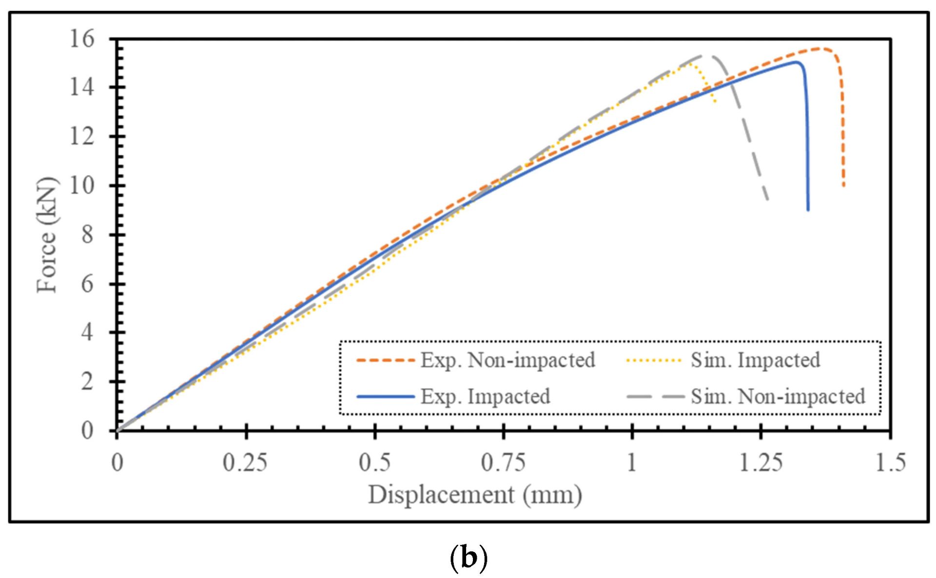
This graph shows the force-displacement curves from tensile tests obtained ex-perimentally (experiments 1–3) and from simulations. Our finite element mod-el was very close to actual results. Source: Ankara Yildirim Beyazit University
In the damage evolution phase, the constitutive relationships for mixed-mode loading employ a single damage variable, SDEG, which characterizes the re-duction in material stiffness across all loading modes. In the analysis, this dam-age variable is calculated using an equivalent traction–separation curve.
The progression of damage within the adhesive layer was tracked in the simula-tions using this parameter, which ranges from 0, indicating no damage, to 1, indicating full damage at an integration point within the cohesive elements. Once the variable reaches a value of 1 at all integration points of a cohesive el-ement, the element loses its load-bearing capacity entirely and is removed from the model.
It is important to emphasize that both stiffness and fracture energy values re-main constant across different loading rates. Accordingly, material properties obtained under quasi-static test conditions were applied uniformly in all nu-merical simulations.
Results
For our FE analysis, we created two models of the bonded joint: quasi-static and dynamic. Our simulation with the quasi-static model indicated that the ad-hesive layer would fail completely if subjected to impact loading. That was not the case in our real-world testing.
These images show the top view of the bonded joint after impact with the bullet. The left image (a) shows the actual joint; the right image (b) shows the numerical model. The bottom image (c) shows the deformation of the joint after tensile testing. Source: Ankara Yildirim Beyazit University
As a result, the corresponding parameters were determined through FE based calibration. The yield strength of epoxy adhesives increases markedly with rising strain rate—reaching nearly threefold under compressive loading and up to fivefold under tensile loading. Importantly, this increase in strength occurs while the adhesive’s elastic modulus remains nearly unchanged between high-strain-rate and quasi-static loading conditions.
Thus, the elevated cohesive strength values incorporated in our dynamic model are consistent with strain-rate sensitivity trends. The dynamic model successfully preserved joint integrity during the impact event.
In the simulation, the bullet penetrates the joint within the first 15 to 20 microseconds and then rebounds after undergoing severe deformation. Notably, the force-displacement curves from post-impact tensile tests, obtained both experimentally and through simulation, showed strong agreement.
As a result, we chose the parameter set from our dynamic model for subsequent analyses. It is also important to highlight that the normal cohesive strength used in our dynamic model is 240 megapascals, which is approximately five times greater than the value reported for quasi-static conditions.
Since the extremities of the overlap region are predominantly subjected to peeling stresses, initial damage typically initiates at these ends and propagates inward under quasi-static tensile loading. Therefore, damage confined to the middle section of the adhesive had limited influence on overall joint performance.
These load-displacement curves show the difference in tensile strength between the bonded joint with a 15-millimeter overlap (a) and the joint with a 25-millimeter overlap (b). Not surprisingly, the latter was stronger. Source: Ankara Yildirim Beyazit University
Influence of Overlap and Substrate Thickness
Our experimental results indicated that the post-impact tensile strength of the assembly with a 15-millimeter overlap exhibited significant degradation, with its load-bearing capacity decreasing by approximately 33 percent. In contrast, the assembly with a 25-millimeter overlap largely maintained its post-impact structural integrity. These findings suggest that increased overlap length miti-gates the adverse mechanical effects of impact loading on the joint’s tensile performance.
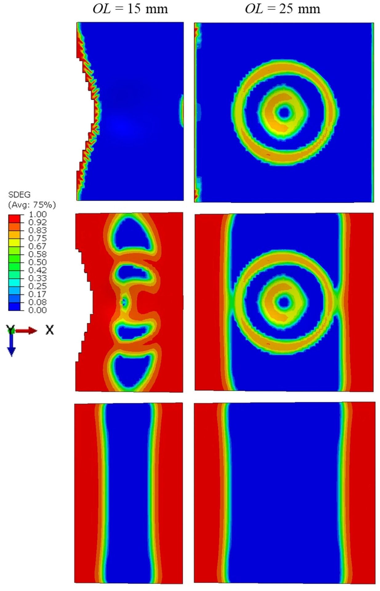
These images show damage distribution on the adhesive layer for the specimens immediately after impact (top), just before failure during tensile testing (middle), and for the control specimens just before failure during tensile testing (bottom). Source: Ankara Yildirim Beyazit University
The damage distribution within the adhesive layer during tensile testing showed a significant contrast between the impacted and non-impacted assemblies. In the non-impacted specimens, damage gradually developed from the central region toward the ends of the adhesive layer, exhibiting a relatively uniform progression along the width of the joint. However, in the impacted samples, the presence of pre-existing damage localized at the center—resulting from the projectile strike—led to a more heterogeneous damage pattern, with prominent damage concentrated in both the central and end regions of the adhesive layer.
The FE analysis of damage progression in the adhesive layer indicated that bullet impact caused damage at the ends for shorter overlap lengths, while for longer overlap lengths, damage was confined to the center. Since the ends of the overlap length bore more tensile loading compared to the central region, joints with an overlap length of 15 millimeters experienced mechanical degradation, whereas those with a 25-millimeter overlap length did not.
When we looked at how substrate thickness affected bond strength after impact, our results were counterintuitive. We found that the tensile strength of the assemblies post-impact decreased as the thickness of the substrates increased. After impact, the tensile strength of assemblies made with 3-millimeter-thick coupons decreased by 17 percent compared with assemblies that had not been hit. In contrast, the tensile strength of assemblies made with 4-millimeter-thick coupons decreased by 34 percent, while the tensile strength of assemblies made with 5-millimeter-thick coupons decreased by 50 percent.
This can be attributed to the growing mismatch in bending stiffness between the adhesive layer and the substrates as the latter become thicker. The adhesive layer possesses significantly lower stiffness compared with the substrates, and this disparity intensifies as the thickness of the substrates increases.
In short, the damage of bonded assemblies after impact is governed by two competing factors: the increasing stiffness mismatch between the substrate and adhesive layers, and the tendency toward more homogenized deformation patterns in the adhesive layer at greater substrate thicknesses.
Looking forward, future studies will explore the damage mechanisms associated with repeated impacts, evaluate the progressive degradation of mechanical performance under varying impact energies and loading sequences, and examine how different overlap lengths influence the residual strength of the joints.
Editor’s note: This article is a summary of a research paper co-authored by Murat Demiral, Ph.D., and Ali Mamedov, Ph.D., of the American University of the Middle East College of Engineering and Technology in Eqaila, Kuwait. To read the entire paper, click here.

ASSEMBLY ONLINE
For more information on adhesive bonding, visit www.assemblymag.com to read these articles: